

MartinRF
-
Content Count
384 -
Joined
-
Last visited
-
Days Won
10
Content Type
Profiles
Media Demo
Forums
Gallery
Calendar
Store
Posts posted by MartinRF
-
-
-
Yeah, I thought about that block too. A ball bearing block for a static load does not make much sense to me.
This study may interest you: http://hem.bredband.net/b262106/Boat/Blockfriction.pdf
/Martin
-
Let me start with a disclaimer: I have no first-hand experience of synthetic standing rigging. My all-steel implementation is very similar but with three extra toggles to minimize fatigue inducing bending of the wires.
To me the implementation shown in your photos looks really good. I would replace what is worn without changing anything.
Others may have wiser advice...
/Martin
-
Nice!
Your sailing grounds are very different from mine. I'll post a video showing mine sometime.
Over canvassed is very relative. Single handed sailing I am fully powered up at 10+ knots -- to windward that is. Fully crewed I have a lot more righting moment.
/Martin
-
Good to hear that.
/Martin
-
Or:
I don't kno the guy who posted this but I know the one who made the video.
/Martin
-
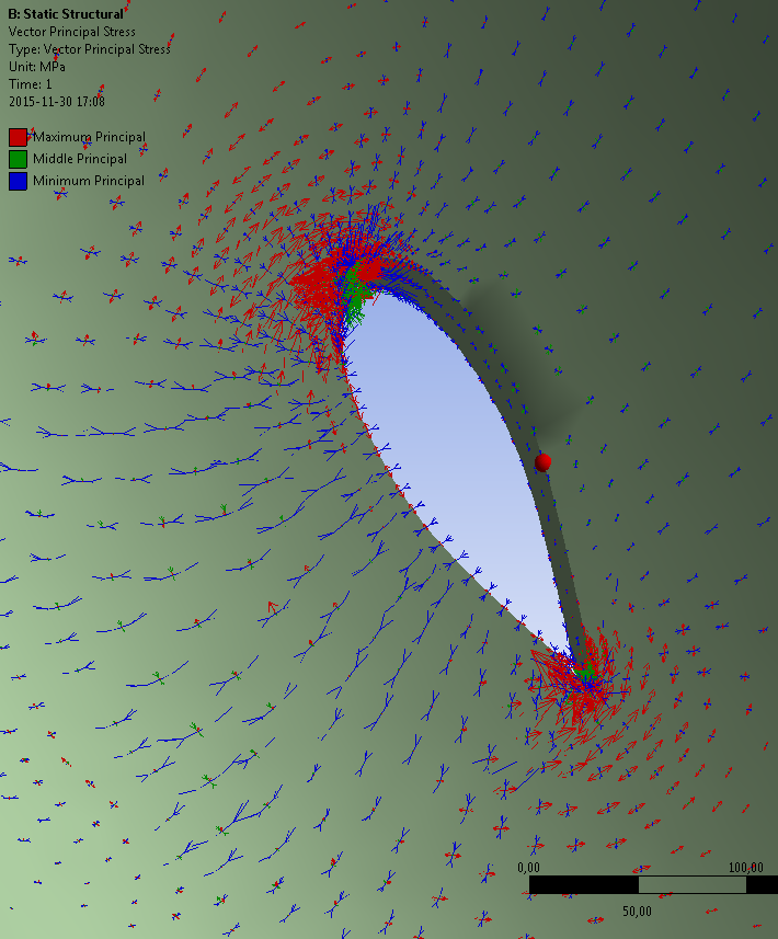
The red ball is on the unloaded side of the dagger board case -- where the board isn't even touching the case.
/Martin
-
Photos or it didn't happen

Here is one I created just before bicycling home today:
This is for the floor-less case with the board pushing on the left side of the hull opening. Red arrows show material in tension and blue arrows to the left of the hole shows the material is in compression.
The red 'ball' is just an indicator showing the centre of rotation when I was manipulating the view.
/Martin
-
 1
1
-
-
Here is the 1986 calculations explained in English. This is kind of brief but I hope it makes sense.
I tried to attach the LibreOffice spreadsheet as well but that was not permitted.
It is my current understanding that real composite experts do not design reiforcements looking like this but it may still be the best option for paxfish. (The presence of the floor calls for a modification in the laminate scheme though.)
One thing not addressed here is how to avoid locally crunching the hull laminate.
/Martin
-
It is easy to impress by using computer generated graphics
I think it does a good job of illustrating where potential problem areas are. Unfortunately it does not offer a way forward to determining proper laminates. The reason is I don't have tools for modelling composites - I have used homogenous, isotropic materials and composites are layered and orthotropic. What I miss is something like this:
It is possibe to make do without this helper add-on by 'drawing' the layers and creating the local coordinate systems manuallly but it would be very time consuming.
But all hope is not lost. Back in 1986 I engneered both boards and hull reinforcements using pen, paper and pocket calculator(*). I actually found my notes the other day and have scanned them for your enjoyment.
Structural_engineering_of_daggerboards_in_1986.pdf
The engineering assumptions are crude but they worked. The boat is 30 years old and we have had no problems with boards or hulls. The original boards where all glass/epoxy and weighed 15 kg a piece. I built deeper and slightly thinner boards in 1995. Using carbon in the main spar of the boards the new ones weighs 13 kg a piece.
I still stick to the same basic engineering principles with few improvements related to better understanding of fatigue limits of composites. See http://hem.bredband.net/b262106/Boat/dagger.html and the documents linked to this page.
I will try to write an explaination to the hull exit reinforcement engineering of 1986 asap, maybe this weekend. It isn't exactly 'rocket science' so it shouldn't be too hard to grasp.
/Martin
*) Martyn Smith once told me he used those tools and no other to engineer the composite structure of Formule TAG.
-
-
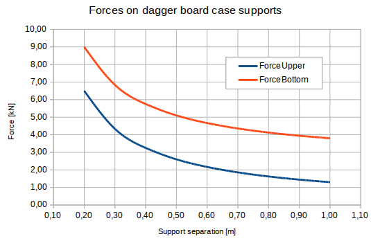
No FEA results yet but I have created an illustration to show the importance of having a healthy separation between upper and lower (boat bottom) supports for the dagger board:
Figures are from my boat and the support separation in the drawings we bought is roughly 20 cm! The Wildfire design looks better in this respect but I think I would prefer even more separation in the interest of reducing material stress.
/Martin
PS Only using free and open software this time: LibreOffice on a Linux system.
-
Using open source programs you mean?
I think that could be done using Freecad and maybe Z88 Aurora or Elmer or the tools collected in CEALinux. I will try that some day but for now I am lazy and use tools I am used to from work.
/Martin
-
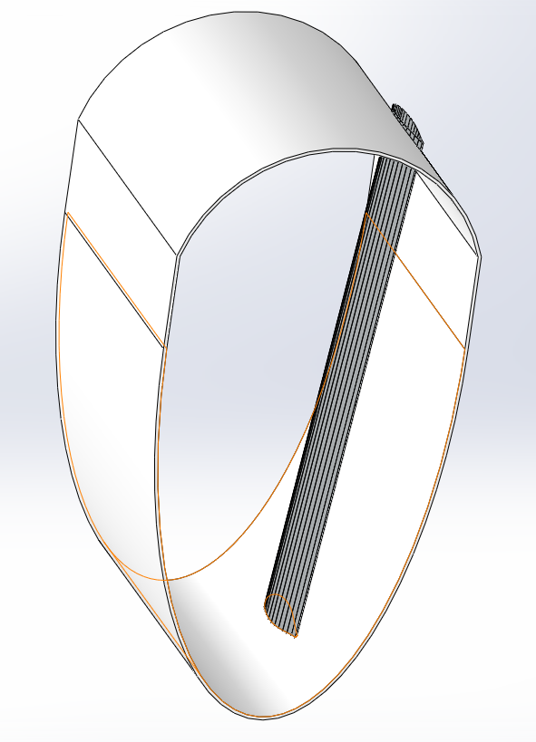
So I couldn't help myself and started modelling the board-hull interaction:
Very much work in progress and I can't guarantee the usefullness of the results but the idea is to load it up with some of those finite elephants and hopefully understand better where stresses go.
/Martin
-
My intention now is to remove the sole roughly 3cm around the opening, grind out any fractured glass from the cracking and lay in many layers of triax and db. No core is compromised in this area as it is all glass. I will then replace the floor and let it make a horizontal column to further distribute the sideways load of the board.
Then I will also attack it in similar fashion from the outside, removing any fractured glass I find and rebuilding. Glass and more resin are on order!
Thanks all for your input. Martin - that is beautiful work on that trunk. I'm surprised you have no sole in that area (or was it added later?) I think the sole would be critical in distributing point loads from the dagger case....
No sole in my boat. None specified and my boat is small with some 1.3 m head room so adding a sole would not really add to comfort.
I see Tennant stuck to the same design we rejected back in 1985. There were a number of things we change in the structural engineering. The only things that have broken are things we did not change such as the cross beams.
Yes, the sole helps distribute the load but only from one side unless you wrap fibres around the dagger board case and spread them onto the sole.
Are you in a hurry? If not, why not spend some time on a bit of proper engineering before slapping on more material?
/Martin
-
Four layers of glass? What kind of glass and why?
Here is what we did 30 years ago instead of following Tennant's instructions. This has worked but I (now) understand there are even better ways of reinforcing this area of the hulls.
Some years ago there was a very long thread on the renovation of a tri called Timberwolf. Unfortunately all photos are missing now.
Having longer boards with the upper support further up in the dagger board case also helps -- less crow-bar like. My dagger boards reach deck even when fully down.
/Martin
-
Underengineered and underbuilt foils are far too common.
There is some information on this here.
I have enclosed a section that works real well. You can scale thickness a bit to fit your dagger board case. The first coordinate is cord and starts at the trailing edge (1) with zero at the leading edge.
Recommended for rudders too.
/Martin
-
On the whole I've been more than happy with the Honda's I've had.
Same here but I have only had one -- an Accord which is 15 years old
(Sorry couldn't resist)
/Martin
-
WRC is not very rot prone to start with.
My boat is mostly not WRC since we could not find enough of it on the Swedish market back then (30 years ago).
I have had no rot problems worth mentioning or remembering but then I have been pretty quick at patching up dents and whatever to stop water ingress and later on made proper repairs.
My main head ache has been UV radiation deteriorating things where I have opted for clear finish. Sooner or later the wood-epoxy bond gives...
Clear finish 'indoors' is a pretty good idea though since it facilitates inspection.
/Martin
-
Hmmm, so you have roughly 1 m more waterline than I have and 50% more empty boat weight. My guess you will only see a small speed increase from changing prop -- you are limited by waterline length. At 7 knots I guess you notice transverse waves in your wake.
/Martin
-
What design by who?
/Martin
-
Very impressive.
/Martin
-
Western red cedar has density of 380 kg/m3. I can't find the sheer properties at hand but I would guess high density PVC foam is superior to cedar by far.
My database on material data says 6 MPa shear strength for WRC @ 320 kg/m³.
200 kg/m³ PVC foam (Termanto) has 4.7 MPa.
Sources: data sheet for PVC, Wood handbook and/or Gougeon's book for wood.
/Martin
-
This may be of interest:
http://hem.bredband.net/b262106/Boat/Sym_vs_Asym.pdf
And perhaps this:
http://hem.bredband.net/b262106/Boat/dagger.html
/Martin
Two videos from the northern hemisphere
in MarineTalk
Posted
A couple of months ago I promised to publish a video showing my sailing grounds. Here it is: https://youtu.be/g2Tt4IvKd5A
Not the most exciting sailing from last season but then I was to busy sailing to dig out the camera.
Some other of my antics recorded on film: commuting to work in snow in November: https://youtu.be/Mmj0my0B07Q
Merry seasonal greetings to all,
/Martin